The SNCR process was introduced in the eighties of the last century and became the Best Available Technology (BAT) for smaller and medium sized combustion plants like WtE plants approximately ten years later. For larger coal-fired power plants, however, the SNCR process was not considered sufficient to maintain the required NOx reduction at all boiler loads and operating conditions. Thus the SCR technology was applied in most cases. While both technologies, low NOx combustion and SNCR, developed rapidly, especially after the turn of the millennium, the application of the SNCR process became a technically and economically viable option to minimize the NOx emissions also in larger power plants.
This paper addresses the different approaches in two power plants in Poland where similar boilers (Type OP 650) with a capacity of 225 MWel are installed. Operating experiences show that with the latest developments and improvements the current NOx levels imposed by the regulators can be assured, and that there is also potential to comply with expected more stringent requirements.
The recent decision of the EU to lower the valid NOx limit for lignite-fired boilers above 100 MWth from 200 to 175 mg NOx/Nm³ opens the door for the application of the SNCR technology. In Germany for instance out of 28 power boilers in operation only four comply with the new regulation.
2. Principles of SNCR Technology
Post-combustion NOx-control technologies which are widely used are the Selective Catalytic Reduction (SCR) process and the Selective Non-Catalytic Reduction (SNCR) process. The major difference between the two systems is that without catalyst the reaction takes place in a temperature range between 900 °C and 1,050 °C whereas with catalyst this temperature window lies between 160 °C and 350 °C. In the SNCR process reagents in aqueous solution (ammonia water, urea solution) or in gaseous form (ammonia) are injected into hot flue gases following the overall post-combustion reactions for
Urea NH2CONH2 + 2 NO + ½ O2 à 2 N2 + CO2 + 2 H2O
or for
Ammonia 4 NH3 + 4 NO + O2 à 4 N2 + 6 H2O.
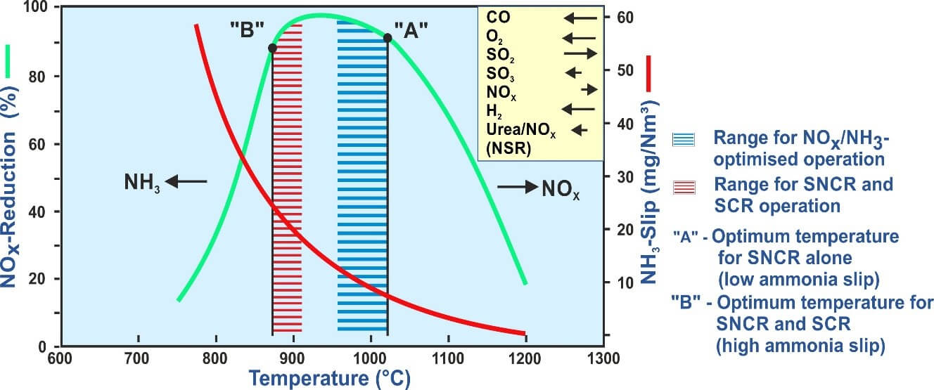
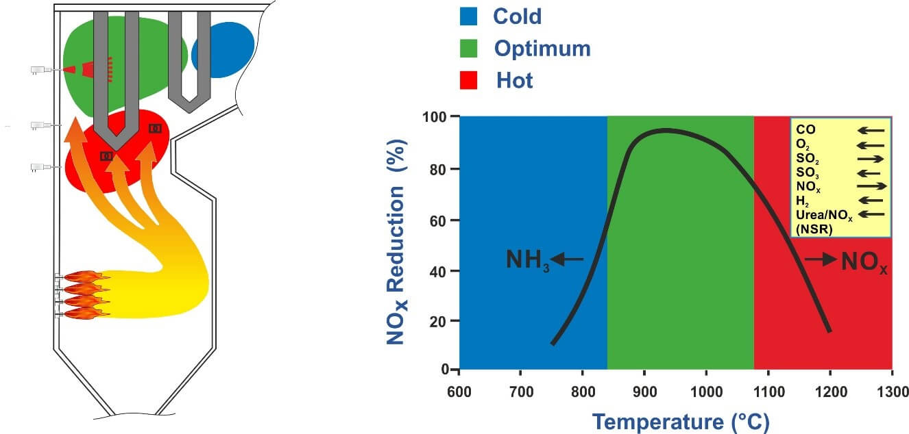
For an optimum NOx reduction with a minimum NH3 slip it is "only" necessary to evenly distribute and thoroughly mix the reagent in the flue gases within the appropriate temperature window. The optimum temperature range to achieve a high NOx reduction combined with a minimum consumption of reagent and a low ammonia slip is rather narrow and depends to a great extent on the flue gas composition (Figure 1).
For coal-fired boilers the optimum temperature lies between about 960 and 1,020 °C. Above this temperature range an increasing amount of ammonia is oxidized, i. e. nitrogen oxides are formed. At lower temperatures, the reaction rate is slowed down causing ammonia slip which may result in the formation of ammonia salts and can lead to secondary problems, downstream the flue gas path. Therefore, ammonia slip should be kept to a minimum.
Since the temperatures over the cross-section in the furnace are rarely uniform and considerable imbalances are often found, special measures need to be taken to identify the right positions for the injectors to distribute the reagent properly into the flue gas under all operating conditions.
Figure 1: NOx Reduction as a function of temperature
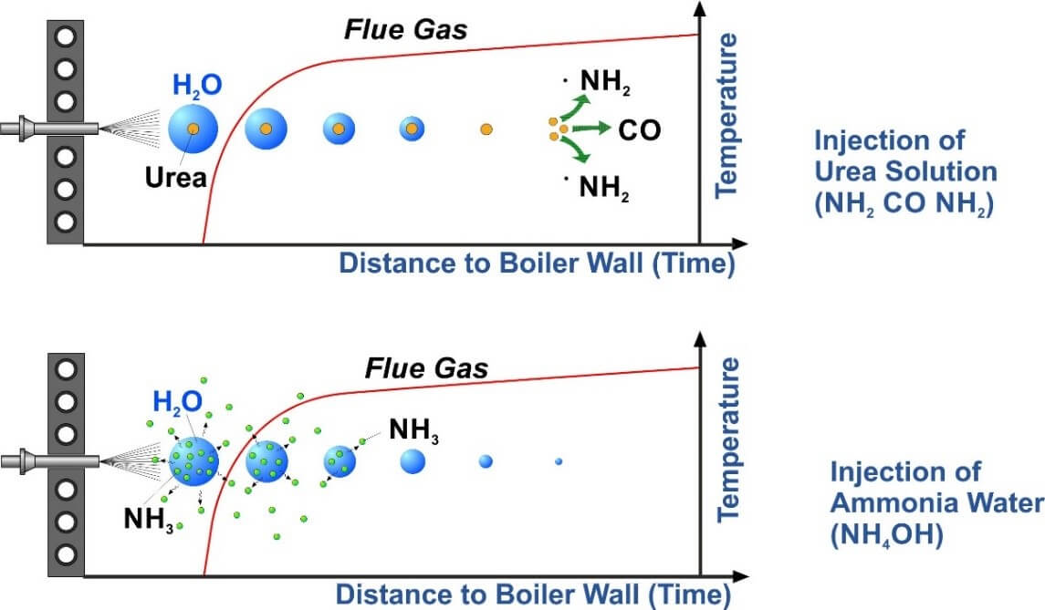
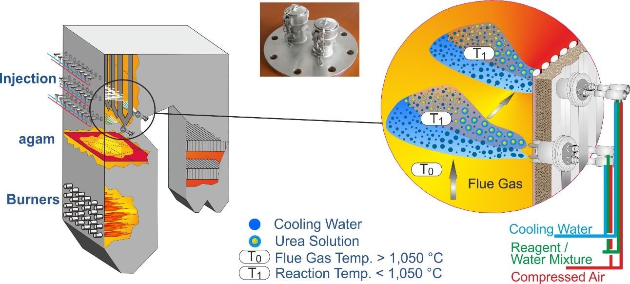
The major difference between ammonia water and urea solution is shown in the strongly simplified diagram in Figure 2. Urea dissolved in water can only be decomposed into reactive NH2-species after the water enclosing the urea particles has been completely evaporated. The position in the furnace where the reaction should take place can be defined in advance by the size and the velocity of the droplets leaving the injection nozzles. By changing the pressures of compressed air and the water/reagent mixture the droplet size and the resulting penetration depth can be adjusted as needed.
Figure 2: NOx Reduction: Urea solution versus ammonia water
If the water droplet is big enough, it is possible to inject into a place that is too hot for NOx reduction. The reagents are now released at the end of the droplets’ trajectories. As a consequence, the reaction takes place in a colder location within the flue gas. The mass of dilution water, which is additionally used as a carrier medium for urea solution, ensures a high penetration depth at rather low energy consumption, and may cool down the flue gas to the desired temperature if necessary. Since urea is very corrosive, impingement of the droplets on the heating surfaces has to be avoided under all circumstances.
Ammonia is a highly volatile reagent which is released near the source of the droplet that is the exit of the nozzle, immediately after the ammonia water has entered the furnace. The NOx reduction will mainly take place in the cooler area near the boiler walls where it is more likely that ammonia slip is generated. To ensure an optimum penetration depth, more energy is required because of the lower mass of ammonia in gaseous form compared to a water droplet. In traditional plants this is accomplished by increasing the pressure of the steam or air flow used as a driving medium.
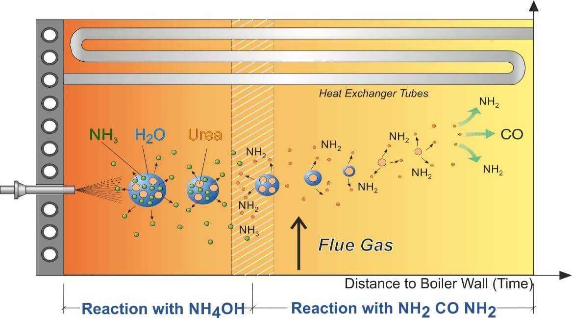
Figure 3: NOx Reduction - Mixing of ammonia water (NH4OH) and urea (NH2 CO NH2)
A homogeneous distribution is very difficult to obtain as flue gases are very viscous. This disadvantage, which has often caused a higher ammonia slip in SNCR plants using ammonia water, can be compensated for to a great extent when dilution water is used as a carrier medium for ammonia water as well.
The greater mass flow of water causes a lower pressure in the jet stream, compared to using compressed air or steam alone. Due to the resulting pressure difference, the surrounding flue gas containing the evaporated ammonia is sucked into the jet stream and mixed with the reagent which carries ammonia almost as far as urea. This concept produces similar results with regard to NOx reduction and ammonia slip as do applications where urea is used as reagent – especially when the flue gas velocity is low like in grate fired boilers where no heat exchangers are built into the furnace.
Ammonia water and urea solution can easily be mixed. Since both reagents have specific characteristics, it was self-evident to combine their features by mixing both reagents or by using them alternatively. Figure 3 shows how the active temperature window can be expanded by using both reagents. By the time the water droplet surrounding the urea particle has evaporated, the NH2 of the decomposed urea will have reached the cooler area, while the ammonia water reacts immediately, close to the boiler wall.
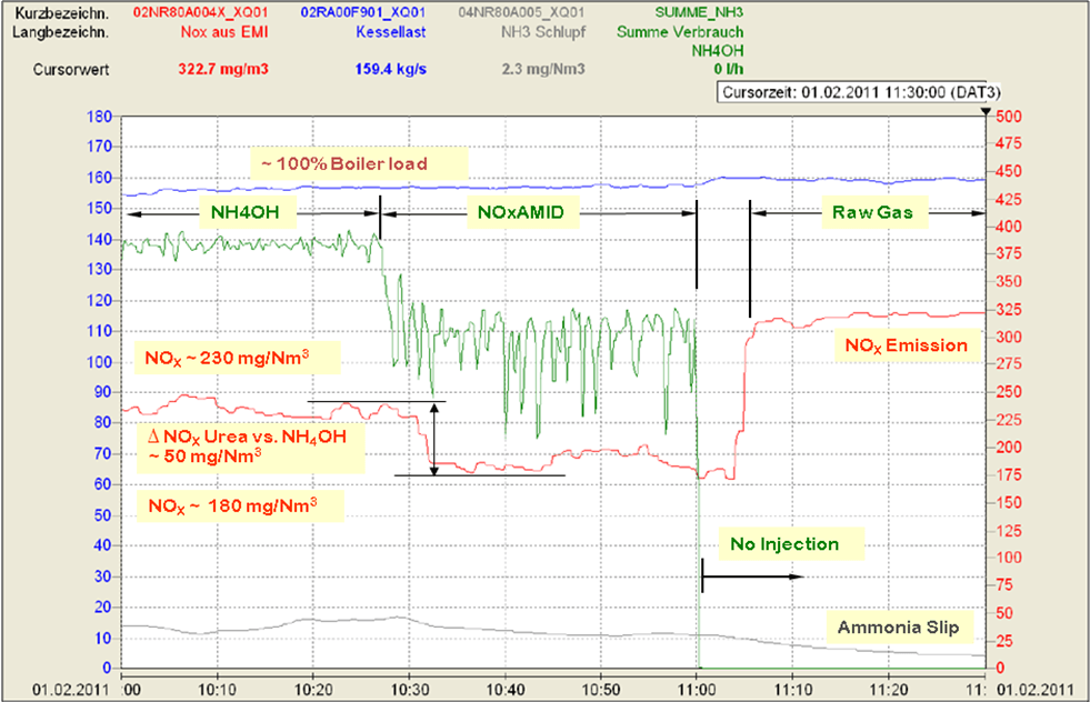
Figure 4: Operating Results – Alternative injection of ammonia water and urea solution (NOxAMID)
The operating results achieved with this combination (TWIN-NOx® Process) are illustrated in Figure 4. The SNCR system for a coal-fired boiler was originally designed for and operated with ammonia water. The diagram shows that after injecting urea solution instead of ammonia water the consumption of reagent and the NOx emission both decrease immediately at full load. This proved that urea is the preferable reagent for this special boiler design with regard to the NOx emissions at full load and when the effective temperature window lies between the heat exchangers.
3. Influences of Design and Operating Conditions on SNCR Performance
The basis of the SNCR technology is to inject the reagents homogenously into the optimum temperature window and to mix them thoroughly with the flue gases. However, in most cases this is not easy to accomplish since there are several major parameters defining the location and accessibility of the optimum temperature window, which are for example:
The boiler design
The design of the combustion chamber
The position of the heat exchangers
The design and configuration of the burners
(profile of temperatures, NOx, flue gas velocities)
The operating conditions in the boiler
The type of fuel
The reagent – urea solution or ammonia water
Figure 5: Typical temperature distribution in a coal-fired two pass boiler
Due to the size of power boilers, the problems that have to be solved by suppliers of SNCR technology are more complex than compared to grate-fired boilers. Especially at full load, temperatures tend to be too high in the areas that are free of built-in components. Consequently, at the furnace exit, the reagent will be oxidized respectively burnt to NOx at higher boiler loads. The temperatures necessary for NOx reduction are often found between the heat exchangers (Figure 5), which are difficult to access or not accessible to injection at all. In addition to this, it is practically impossible to measure or determine the velocities and directions of the flue gases.
4. SNCR Application in Coal-Fired Boilers in Poland
In Poland, where a number of the same type OP 650 with a rated capacity of 225 MWel are in operation, the results of operating experiences with coal-fired boilers prove that even minor differences in the design of the boilers and the configuration of the burners may have a major impact on the flue gas flow and temperature distribution, and consequently on the efficiency of the SNCR process.
By far the best results could be achieved in boilers with corner-firing, like in the power plant in Polaniec, Poland, where during trials reduction rates of close to 60 % were realized. In corner-fired boilers the flue gases are circulated, which has several positive effects on the SNCR process as opposed to front-fired boilers or boilers with boxer-firing. In corner-fired boilers, the flue gases have a lower temperature when entering the heat exchangers, the temperature imbalances are less extreme and the formation of flue gas streams is reduced.
With computer simulations it is possible to provide rather detailed information on all parameters relevant to the SNCR process, like temperature profile, direction and velocities of the flue gases, and distribution of components (NOx, CO, O2 etc.). This offers further potential to improve the performance of SNCR.
5. Location A – SNCR with In-Furnace Lances
In the power plant at Location A in Poland, six coal-fired boilers type OP 650 (Figure 6) are operated with front-firing. After replacing the burners and retrofitting the supply of combustion air, a commercial SNCR plant was installed in one of the boilers. Earlier operating experiences with other boilers and the results of the previous tests with similar boilers were applied as basis for the design of the SNCR system.
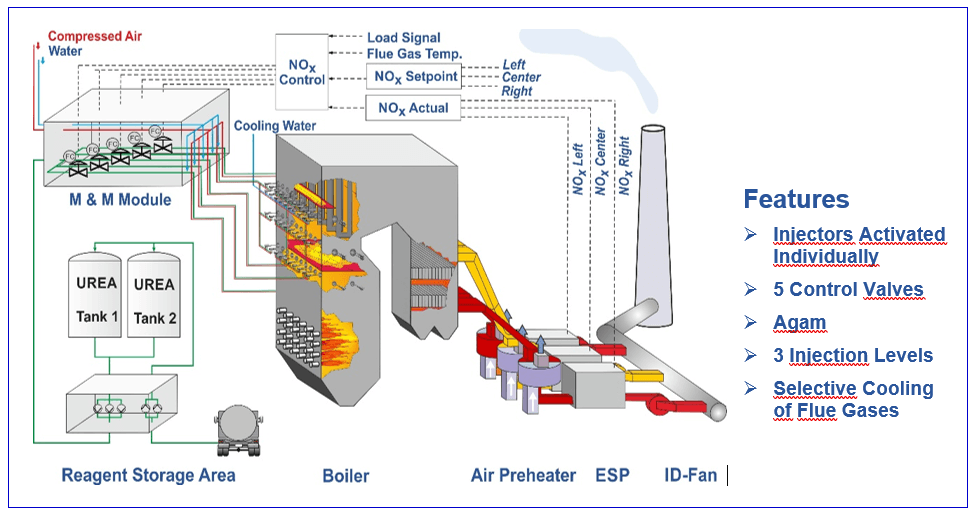
Figure 6: Flow diagram of coal-fired boiler OP650 with SNCR
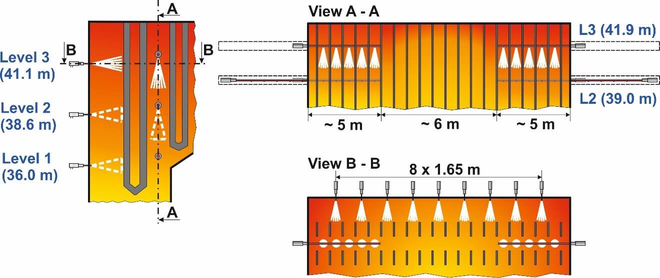
The design includes three injection levels with lances for the injection of urea solution where each lance can be activated individually, enabling the plant to react to changes of load and temperature. Due to the extreme temperature imbalances of up to 200 K, which had been measured at the beginning of the design phase, an acoustic temperature measurement system (agam) with two levels was installed. The second agam level allows for a more precise temperature measurement near the upper injection level and is used to determine the temperature gradient between the two agam levels. The first SNCR plant (K2) was commissioned in March 2012 and handed over to the customer shortly after. Since then the plant has been in continuous operation complying with the NOx regulation < 200 mg/Nm³ at all boiler loads. The last SNCR (K5) was handed over in December 2016.
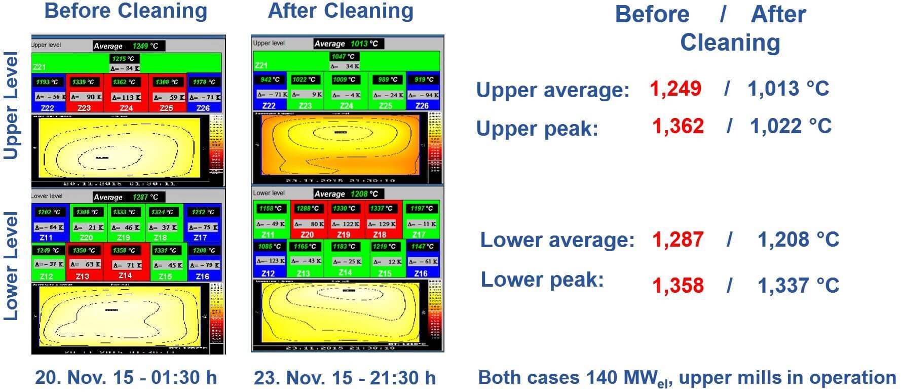
Figure 7: Impact of boiler cleaning on flue gas temperatures
After commissioning of the first boiler, the flue gas temperatures at full load were found to be higher than in measurements prior to the design of the SNCR. There were also considerable peaks and imbalances in the temperature profile and NOx raw gas concentration. A further challenge in these boilers is that deposits on the heat exchangers accumulate so much that the flue gas temperature increases by up to 300 °C between two cleaning cycles (Figure 7).
Therefore, the upper injection level in the second boiler was moved up to a higher position, to a place where the temperatures are colder, taking into account that less flue gas volume would be reached with reagent. Although the guaranteed NOx levels in the first boiler had been met, an optimization process was started in order to analyze the results and find measures to improve the performance of the SNCR further. To react better to the temperature imbalances, and vary the injection of reagents depending on the NOx mass flow in this area three NOx control valves were installed. This resulted in lower ammonia slip both in the flue gas and the ash, and in a reduction of ammonia water consumption.
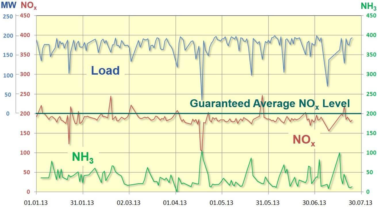
Combined with the primary measures, the guaranteed NOx levels of < 200 mg/Nm³ are reached at all operating conditions. The average NH3 load of the fly-ash measured in the period from January 1, 2013 to July 30, 2013 was 37 mg/Nm³ (Figure 8).
Since the future NOx limits in the EU of 150 or 175 mg/Nm³ cannot be guaranteed for all operating conditions with the present design, other alternatives had to be looked for to improve the performance of the SNCR.
Figure 8: Long-term performance data of SNCR in coal-fired boiler (225 MWel)
If flue gas temperatures are too hot for the SNCR technology in those areas which are accessible to the injection of reagents, one option is to cool down the flue gases with water to the optimum temperature. In larger boilers where the reagents are practically always injected at right angles into the flue gas flow, the installation of an additional injection level which can be operated with cooling water alone, when needed, has proven to be successful in continuous operation. With this concept cooling water is only applied when temperatures are too high.
Figure 9: Selective Cooling of flue gases for coal-fired boilers
At lower loads respectively temperatures, the water is switched off. The droplet spectrum for the injection of reagents is not changed. However, the disadvantage is that temperature imbalances may lead to higher ammonia slip, because the cooling also takes place in areas with optimum flue gas temperatures where cooling is not needed.
Figure 10: Configuration of injectors at front wall and in-furnace lances
In other places, good results have been achieved with Selective Cooling of the flue gases which also requires an additional injection level for cooling water beneath the upper injection level. However, instead of covering the whole level with cooling water, it is injected only in those areas which are too hot (Figure 9), i. e. depending on the temperature profile individual lances or groups of lances are activated.
Figure 11: Flow diagram with injection from front wall and in-furnace lances
However, since flue gas temperatures at the furnace outlet in Location A reach 1,350 or even 1,400 °C at full load, the application of Selective Cooling would not make sense because the quantity of cooling water required for cooling the flue gases from 1,400 °C down to the effective temperature window of approx. 980 to 1,050 °C is so high that the efficiency of the boilers would be affected too much. This also means that about 50 % of the flue gas are not usable for NOx reduction because of too high temperatures.
Figure 12: Reagent injection – Nozzle configuration of in-furnace lances
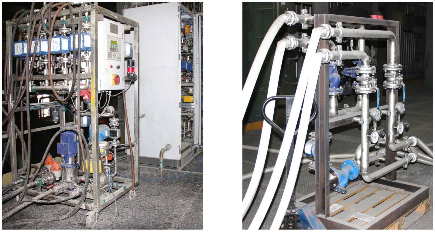
Figure 13: Mobile mixing and metering module; Module for cooling water
In order to inject reagent in the flue gas which cannot be treated because of too high temperature at the end of the furnace, a different approach has been tested. Assuming that the flue gas temperatures between the heat exchangers are more favorable, two SNCR in-furnace lances with a length of only four meters have been installed in each side wall of the boiler in the path between the first and second super heater (Figures 10, 11, 12). The distance between the two side walls of the boilers is 16 m. Figure 13 shows the temporary mixing and metering module for the in-furnace lances and the module for cooling water.
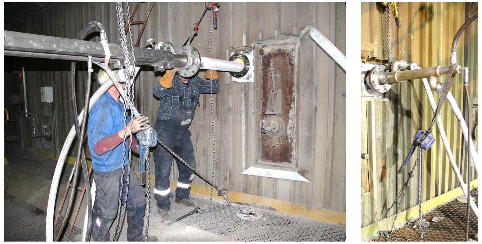
Since one lance of 4 m length already weighs approx. 150 kg it is very difficult to install the lances manually into the boiler wall and take them out again (Figure 14). It was assumed that test results with those short lances would provide sufficient information to estimate the additional potential for performance in commercial operation if longer lances are used, which would be pushed into the boiler and retracted automatically on devices similar to the retraction devices for soot blowers.
Figure 14: Installation of in-furnace lances for trial operation
The automatically activated retractors can be taken out of the flue gas flow for instance at lower boiler loads when they are not needed. In emergency cases when the supply of cooling water fails, they have to be taken out immediately to protect the lances.
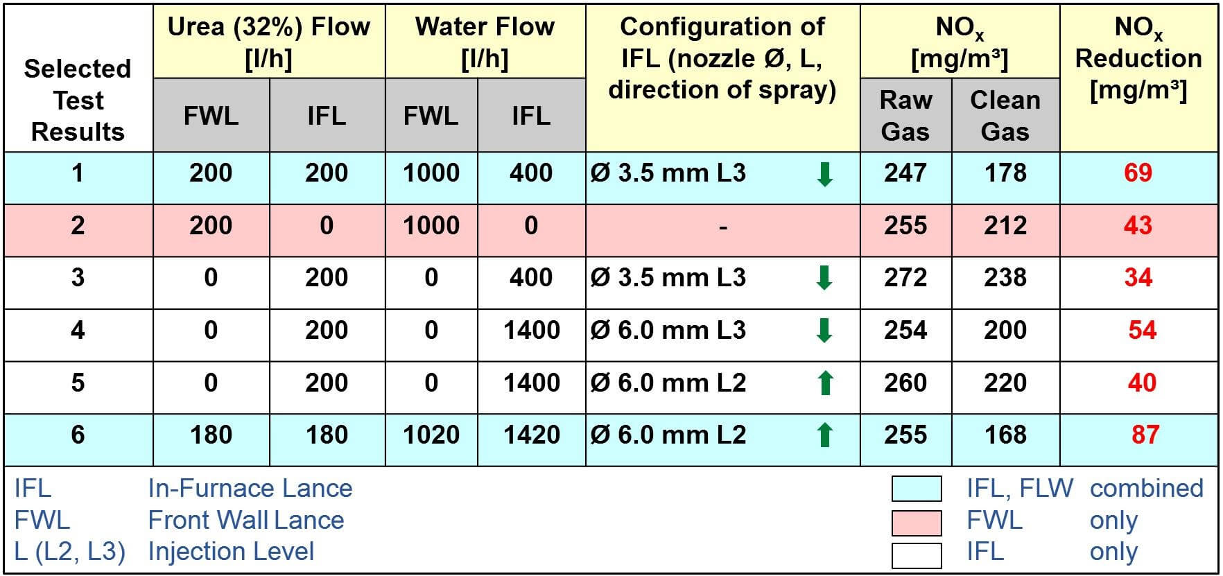
The test results are very positive and show that the present NOx reduction can be increased to more than 100 mg/Nm³ in total if in-furnace lances are used in addition to the injection from the front wall (Table 1). If four in-furnace lances are used and the lengths of the lances are extended to cover more distance between the boiler walls, the NOx limits of 175 or 150 mg/Nm³ will be reached. It also could be an option to operate the boiler with higher NOx baselines in order to decrease the risk of causing corrosion of the walls in the combustion chamber due to the lack of O2.
Table 1: Test results with different lance configurations
6. Location B – SNCR with Selective Cooling
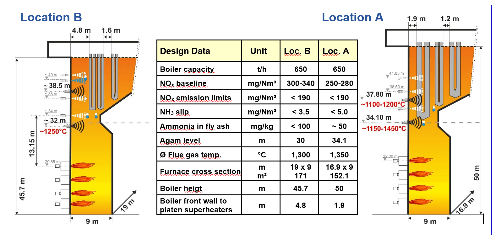
In April 2015, M&S was awarded with the contract to install four SNCR plants in the power plant of Location B. The boilers are of the same type as in Location A, OP 650, with a capacity of 225 MWel. However, some design features are different as shown in Figure 15 and have a considerable impact on the performance of SNCR as can be seen in Table 2.
Figure 15: Design data of Location A and Location B
In Location B, the arrangement of the heat exchangers is much more favorable than in Location A. The width of the boiler of 19 m in Location B compared to 16.9 m in Location A, and the distance from the boiler front walls to the platen super heaters (4.8 m in Location B vs. 1.9 m in Location A) leave almost three times more space for the reaction of the reagent with the NOx in the flue gas (91.2 m² vs. 32.1 m²) in the upper injection level, which is relevant for the SNCR performance at higher loads. Furthermore, the larger cross-section of the furnace in Location B (171 m² vs. 152.1 m²) result in lower flue gas velocities, lower flue gas temperatures at the reaction locations, and longer residence time for the NOx reduction.
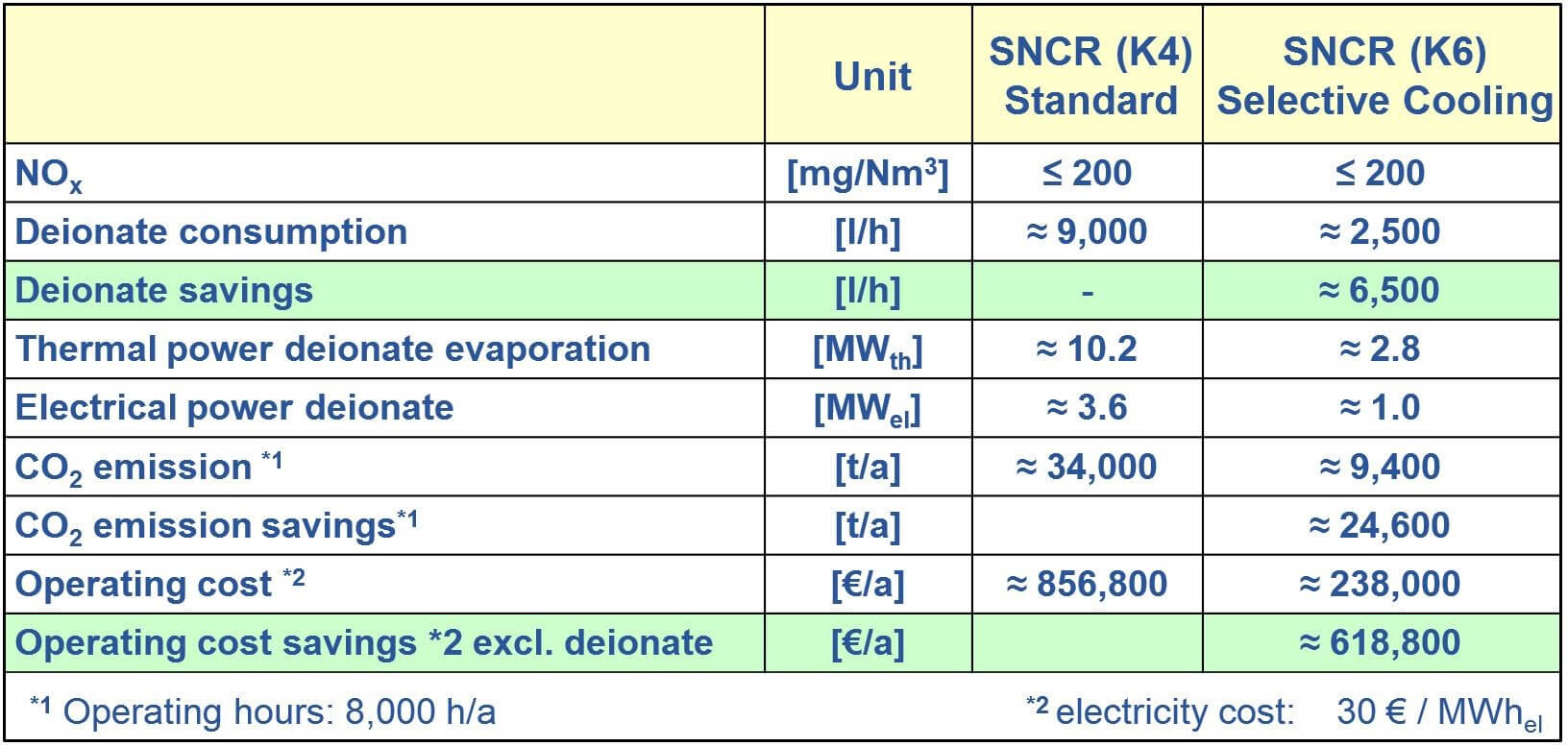
Table 2: Comparison of standard SNCR vs. SNCR with Selective Coolingregarding water consumption
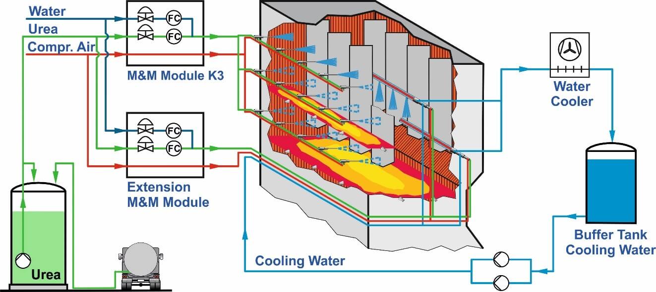
The concept for boiler K6 was elaborated based on the boiler design, the expected lower flue gas temperatures, the performance of the standard SNCR which had been installed and commissioned at boiler K4, and the results and experiences in Location A. Figure 16 shows the mixing and metering modules of Location B and the injection lances.
Figure 16: Location B - Mixing and metering module; Injection lances for reagent and selective cooling
The significant difference to Location A is that injection lances for Selective Cooling, installed below the highest injection level for the reagent, could be utilized because the flue gas temperatures in this position were lower than in Location A and the space between the front wall and the first super heater was larger, which resulted in a much better performance of the SNCR system.
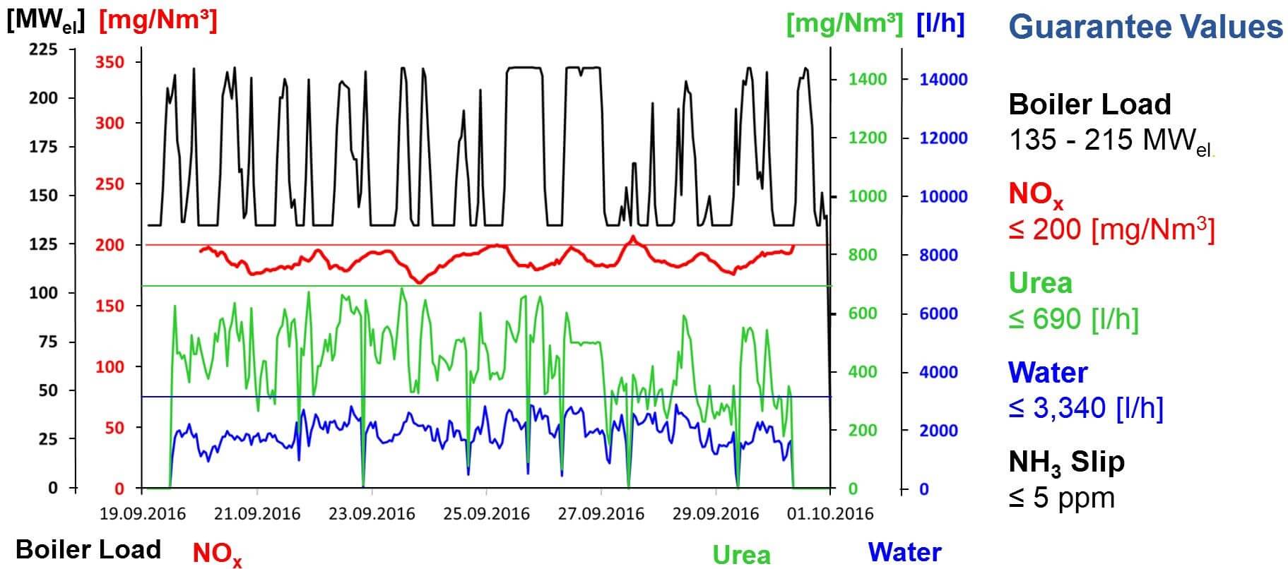
Figures 17 and 18 show the performance of the SNCR at boiler loads of 215 MWel and 130 MWel during the two weeks reliability run (Figure 19). All guarantee values were achieved at all loads.
Figure 17: Selective Cooling of flue gases - Operating data at full load (215 MWel)
Figure 18: Selective Cooling of flue gases - Operating data at partial load (130 MWel)
It is remarkable that the total water consumption which was an important issue during contract negotiations is approximately 1,000 l/h lower than the guaranteed maximum of 3,500 l/h and ca. 6,500 l/h lower than the consumption of the standard SNCR installed at boiler K4. These results demonstrate impressively that the Selective Cooling is superior to other SNCR technologies for the discussed type of power boilers and that a significant amount of operating cost can be saved.
Figure 19: Performance data during two-week reliability run at Location B
7. Adaptive Flue Gas Cooling
Injecting of water offers the great benefit that extensive and costly modifications of the boiler can be avoided when the flue gases are cooled down before entering the heat exchangers. The major disadvantage, however, is that depending on the operating hours at high boiler loads in which water cooling is necessary, the efficiency of the boiler is affected because of the energy needed to evaporate the water in the flue gas. Selective Cooling is already a big step forward to improve the performance of SNCR by cooling down the flue gases.
Figure 20: Principle of Adaptive Flue Gas Cooling
However, a better solution is to control the amount of water more precisely in order to further decrease the consumption of cooling water.
To realize this objective a temperature measurement system which generates a temperature profile has to be installed above the upper injection level in the furnace (Figure 20).
The temperatures are constantly being measured online and average flue gas temperatures are calculated in defined sections which are assigned to single injectors or groups of injectors.
Without injection of reagent
With injection of reagent only
With injection of reagent and cooling water simultaneously.
At the lowest level, injection of cooling water is generally not needed, since the injectors will be switched to higher levels as the flue gas temperatures increase with the load.
With the described concept the temperatures and the influence of the injected liquids, i. e. reagent/water-mixture and cooling water, can be measured. Based on the various temperatures the flow of cooling water can be adapted as needed to maintain the optimum temperatures within the injection level in order to obtain efficient NOx reduction and low ammonia slip. Furthermore, the activation of the lances for reagent can be determined more precisely when temperatures are measured in two levels.
To achieve this, another temperature measurement system has to be installed for measuring the flue gas temperatures above the lowest injection level as described for the top level.
1.1. Defining Flue Gas Velocity
It is often neglected that apart from the flue gas temperatures, the flue gas velocities at different injection positions, are of equal importance for the efficiency of the SNCR process. The NOx to be reduced depends on the NOx baseline at the injection locations and the target NOx.
NOx mass flow [kg/h] = NOx concentration [mg/m³] * flue gas mass flow [m³/h]
There is high probability that in some areas where the flue gas velocities are low, too much reagent is injected in areas with similar NOx concentration causing higher ammonia slip since the reagents do not find enough partners for the chemical reaction. To avoid this, the flow of reagent should be reduced or stopped to decrease the consumption of reagent and minimize ammonia slip.
With this arrangement of the temperature measurement systems in two levels, the temperatures in the levels and sectors can be compared and the temperature gradient between the levels can be defined more correctly than with traditional methods.
Since hot flue gases have a higher natural draught and slower flue gases are cooled down more at the boiler walls and heat exchangers, higher temperature differences indicate a slower flue gas velocity compared to areas with smaller temperature differences (Figure 21).
This information is the basis to control, respectively adjust the flow of reagent to the corresponding injectors or groups of injectors with the objective to optimize NOx reduction and to minimize ammonia slip.
Figure 21: NOx Mass flow profile
If measuring equipment were used which provides data of other components like NOx, CO, O2, etc. in addition to the temperatures, these data could be incorporated into the control of the SNCR as well as into a further optimized distribution of the reagent across the furnace for better performance of the SNCR.
8. Summary and Outlook
In smaller combustion plants, e. g. those which burn waste or biomass, the SNCR process represents an industry standard and state-of-the-art method. In the meantime, operating experiences in large combustion plants with a capacity of > 200 MWel have shown over the past few years that SNCR can safely and reliably achieve the NOx level < 200 mg/Nm³ which has been enforced by EU legislation in 2016. Different injection concepts can be used separately or in combination in order to guarantee yearly average NOx levels of < 175 mg/Nm³ for lignite-fired boilers and < 150 mg/Nm³ for hard-coal fired boilers in the future.
The initial results of the newer technologies, like the changing of individual lances, the TWIN-NOx® process, the Selective Cooling and the combination of these methods with primary measures indicate that there is further potential for developments. The next step will be plants with boiler capacities from 300 to 500 MWel.
9. Literature
von der Heide, Bernd: “SNCR-process – Best Available Technology for NOx Reduction in Waste to Energy Plants”, Power-Gen Europe, Milan, June 3 – 5, 2008
von der Heide, Bernd: “Advanced SNCR Technology for Power Plants”, Power-Gen International, Las Vegas, December 13 – 15, 2011
von der Heide, Bernd: “SNCR-Verfahren der Zukunft für Großfeuerungsanlagen – Konzepte, Erfahrungen, TWIN-NOx®-Verfahren“ in: Michael Beckmann, Antonio Hurgado (Hrsg.): Kraftwerkstechnik – Sichere und nachhaltige Energieversorgung – Band 4. Neuruppin: TK Verlag Karl Thomé-Kosmiensky, 2012, S. 623 – 635
Moorman, Frans; Stubenhöfer, Claus; von der Heide, Bernd: „Replacement of an SCR DENOX system by a highly efficient SNCR in a waste-to-energy plant in the Netherlands“ in VGB POWERTECH Volume 93 – Issue 12/2013
von der Heide, Bernd: „Cost Savings and Improvements of SNCR Performance with Selective Cooling in Coal-Fired Boilers (225 MWel)”, VGB Workshop “Flue Gas Cleaning”, Lisbon, May 3 – 5, 2017
Future-Oriented SNCR Technologies – Application and Advantages of Selective Cooling in Large Coal-Fired Boilers
The SNCR process was introduced in the eighties of the last century and became the Best Available Technology (BAT) for smaller and medium sized combustion plants like WtE plants approximately ten years later. For larger coal-fired power plants, however, the SNCR process was not considered sufficient to maintain the required NOx reduction at all boiler loads and operating conditions. Thus the SCR technology was applied in most cases. While both technologies, low NOx combustion and SNCR, developed rapidly, especially after the turn of the millennium, the application of the SNCR process became a technically and economically viable option to minimize the NOx emissions also in larger power plants.
This paper addresses the different approaches in two power plants in Poland where similar boilers (Type OP 650) with a capacity of 225 MWel are installed. Operating experiences show that with the latest developments and improvements the current NOx levels imposed by the regulators can be assured, and that there is also potential to comply with expected more stringent requirements.
The recent decision of the EU to lower the valid NOx limit for lignite-fired boilers above 100 MWth from 200 to 175 mg NOx/Nm³ opens the door for the application of the SNCR technology. In Germany for instance out of 28 power boilers in operation only four comply with the new regulation.
2. Principles of SNCR Technology
Post-combustion NOx-control technologies which are widely used are the Selective Catalytic Reduction (SCR) process and the Selective Non-Catalytic Reduction (SNCR) process. The major difference between the two systems is that without catalyst the reaction takes place in a temperature range between 900 °C and 1,050 °C whereas with catalyst this temperature window lies between 160 °C and 350 °C. In the SNCR process reagents in aqueous solution (ammonia water, urea solution) or in gaseous form (ammonia) are injected into hot flue gases following the overall post-combustion reactions for
Urea NH2CONH2 + 2 NO + ½ O2 à 2 N2 + CO2 + 2 H2O
or for
Ammonia 4 NH3 + 4 NO + O2 à 4 N2 + 6 H2O.
For an optimum NOx reduction with a minimum NH3 slip it is "only" necessary to evenly distribute and thoroughly mix the reagent in the flue gases within the appropriate temperature window. The optimum temperature range to achieve a high NOx reduction combined with a minimum consumption of reagent and a low ammonia slip is rather narrow and depends to a great extent on the flue gas composition (Figure 1).
For coal-fired boilers the optimum temperature lies between about 960 and 1,020 °C. Above this temperature range an increasing amount of ammonia is oxidized, i. e. nitrogen oxides are formed. At lower temperatures, the reaction rate is slowed down causing ammonia slip which may result in the formation of ammonia salts and can lead to secondary problems, downstream the flue gas path. Therefore, ammonia slip should be kept to a minimum.
Since the temperatures over the cross-section in the furnace are rarely uniform and considerable imbalances are often found, special measures need to be taken to identify the right positions for the injectors to distribute the reagent properly into the flue gas under all operating conditions.
Figure 1: NOx Reduction as a function of temperature
The major difference between ammonia water and urea solution is shown in the strongly simplified diagram in Figure 2. Urea dissolved in water can only be decomposed into reactive NH2-species after the water enclosing the urea particles has been completely evaporated. The position in the furnace where the reaction should take place can be defined in advance by the size and the velocity of the droplets leaving the injection nozzles. By changing the pressures of compressed air and the water/reagent mixture the droplet size and the resulting penetration depth can be adjusted as needed.
Figure 2: NOx Reduction: Urea solution versus ammonia water
If the water droplet is big enough, it is possible to inject into a place that is too hot for NOx reduction. The reagents are now released at the end of the droplets’ trajectories. As a consequence, the reaction takes place in a colder location within the flue gas. The mass of dilution water, which is additionally used as a carrier medium for urea solution, ensures a high penetration depth at rather low energy consumption, and may cool down the flue gas to the desired temperature if necessary. Since urea is very corrosive, impingement of the droplets on the heating surfaces has to be avoided under all circumstances.
Ammonia is a highly volatile reagent which is released near the source of the droplet that is the exit of the nozzle, immediately after the ammonia water has entered the furnace. The NOx reduction will mainly take place in the cooler area near the boiler walls where it is more likely that ammonia slip is generated. To ensure an optimum penetration depth, more energy is required because of the lower mass of ammonia in gaseous form compared to a water droplet. In traditional plants this is accomplished by increasing the pressure of the steam or air flow used as a driving medium.
Figure 3: NOx Reduction - Mixing of ammonia water (NH4OH) and urea (NH2 CO NH2)
A homogeneous distribution is very difficult to obtain as flue gases are very viscous. This disadvantage, which has often caused a higher ammonia slip in SNCR plants using ammonia water, can be compensated for to a great extent when dilution water is used as a carrier medium for ammonia water as well.
The greater mass flow of water causes a lower pressure in the jet stream, compared to using compressed air or steam alone. Due to the resulting pressure difference, the surrounding flue gas containing the evaporated ammonia is sucked into the jet stream and mixed with the reagent which carries ammonia almost as far as urea. This concept produces similar results with regard to NOx reduction and ammonia slip as do applications where urea is used as reagent – especially when the flue gas velocity is low like in grate fired boilers where no heat exchangers are built into the furnace.
Ammonia water and urea solution can easily be mixed. Since both reagents have specific characteristics, it was self-evident to combine their features by mixing both reagents or by using them alternatively. Figure 3 shows how the active temperature window can be expanded by using both reagents. By the time the water droplet surrounding the urea particle has evaporated, the NH2 of the decomposed urea will have reached the cooler area, while the ammonia water reacts immediately, close to the boiler wall.
Figure 4: Operating Results – Alternative injection of ammonia water and urea solution (NOxAMID)
The operating results achieved with this combination (TWIN-NOx® Process) are illustrated in Figure 4. The SNCR system for a coal-fired boiler was originally designed for and operated with ammonia water. The diagram shows that after injecting urea solution instead of ammonia water the consumption of reagent and the NOx emission both decrease immediately at full load. This proved that urea is the preferable reagent for this special boiler design with regard to the NOx emissions at full load and when the effective temperature window lies between the heat exchangers.
3. Influences of Design and Operating Conditions on SNCR Performance
The basis of the SNCR technology is to inject the reagents homogenously into the optimum temperature window and to mix them thoroughly with the flue gases. However, in most cases this is not easy to accomplish since there are several major parameters defining the location and accessibility of the optimum temperature window, which are for example:
The boiler design
The design of the combustion chamber
The position of the heat exchangers
The design and configuration of the burners
(profile of temperatures, NOx, flue gas velocities)
The operating conditions in the boiler
The type of fuel
The reagent – urea solution or ammonia water
Figure 5: Typical temperature distribution in a coal-fired two pass boiler
Due to the size of power boilers, the problems that have to be solved by suppliers of SNCR technology are more complex than compared to grate-fired boilers. Especially at full load, temperatures tend to be too high in the areas that are free of built-in components. Consequently, at the furnace exit, the reagent will be oxidized respectively burnt to NOx at higher boiler loads. The temperatures necessary for NOx reduction are often found between the heat exchangers (Figure 5), which are difficult to access or not accessible to injection at all. In addition to this, it is practically impossible to measure or determine the velocities and directions of the flue gases.
4. SNCR Application in Coal-Fired Boilers in Poland
In Poland, where a number of the same type OP 650 with a rated capacity of 225 MWel are in operation, the results of operating experiences with coal-fired boilers prove that even minor differences in the design of the boilers and the configuration of the burners may have a major impact on the flue gas flow and temperature distribution, and consequently on the efficiency of the SNCR process.
By far the best results could be achieved in boilers with corner-firing, like in the power plant in Polaniec, Poland, where during trials reduction rates of close to 60 % were realized. In corner-fired boilers the flue gases are circulated, which has several positive effects on the SNCR process as opposed to front-fired boilers or boilers with boxer-firing. In corner-fired boilers, the flue gases have a lower temperature when entering the heat exchangers, the temperature imbalances are less extreme and the formation of flue gas streams is reduced.
With computer simulations it is possible to provide rather detailed information on all parameters relevant to the SNCR process, like temperature profile, direction and velocities of the flue gases, and distribution of components (NOx, CO, O2 etc.). This offers further potential to improve the performance of SNCR.
5. Location A – SNCR with In-Furnace Lances
In the power plant at Location A in Poland, six coal-fired boilers type OP 650 (Figure 6) are operated with front-firing. After replacing the burners and retrofitting the supply of combustion air, a commercial SNCR plant was installed in one of the boilers. Earlier operating experiences with other boilers and the results of the previous tests with similar boilers were applied as basis for the design of the SNCR system.
Figure 6: Flow diagram of coal-fired boiler OP650 with SNCR
The design includes three injection levels with lances for the injection of urea solution where each lance can be activated individually, enabling the plant to react to changes of load and temperature. Due to the extreme temperature imbalances of up to 200 K, which had been measured at the beginning of the design phase, an acoustic temperature measurement system (agam) with two levels was installed. The second agam level allows for a more precise temperature measurement near the upper injection level and is used to determine the temperature gradient between the two agam levels. The first SNCR plant (K2) was commissioned in March 2012 and handed over to the customer shortly after. Since then the plant has been in continuous operation complying with the NOx regulation < 200 mg/Nm³ at all boiler loads. The last SNCR (K5) was handed over in December 2016.
Figure 7: Impact of boiler cleaning on flue gas temperatures
After commissioning of the first boiler, the flue gas temperatures at full load were found to be higher than in measurements prior to the design of the SNCR. There were also considerable peaks and imbalances in the temperature profile and NOx raw gas concentration. A further challenge in these boilers is that deposits on the heat exchangers accumulate so much that the flue gas temperature increases by up to 300 °C between two cleaning cycles (Figure 7).
Therefore, the upper injection level in the second boiler was moved up to a higher position, to a place where the temperatures are colder, taking into account that less flue gas volume would be reached with reagent. Although the guaranteed NOx levels in the first boiler had been met, an optimization process was started in order to analyze the results and find measures to improve the performance of the SNCR further. To react better to the temperature imbalances, and vary the injection of reagents depending on the NOx mass flow in this area three NOx control valves were installed. This resulted in lower ammonia slip both in the flue gas and the ash, and in a reduction of ammonia water consumption.
Combined with the primary measures, the guaranteed NOx levels of < 200 mg/Nm³ are reached at all operating conditions. The average NH3 load of the fly-ash measured in the period from January 1, 2013 to July 30, 2013 was 37 mg/Nm³ (Figure 8).
Since the future NOx limits in the EU of 150 or 175 mg/Nm³ cannot be guaranteed for all operating conditions with the present design, other alternatives had to be looked for to improve the performance of the SNCR.
Figure 8: Long-term performance data of SNCR in coal-fired boiler (225 MWel)
If flue gas temperatures are too hot for the SNCR technology in those areas which are accessible to the injection of reagents, one option is to cool down the flue gases with water to the optimum temperature. In larger boilers where the reagents are practically always injected at right angles into the flue gas flow, the installation of an additional injection level which can be operated with cooling water alone, when needed, has proven to be successful in continuous operation. With this concept cooling water is only applied when temperatures are too high.
Figure 9: Selective Cooling of flue gases for coal-fired boilers
At lower loads respectively temperatures, the water is switched off. The droplet spectrum for the injection of reagents is not changed. However, the disadvantage is that temperature imbalances may lead to higher ammonia slip, because the cooling also takes place in areas with optimum flue gas temperatures where cooling is not needed.
Figure 10: Configuration of injectors at front wall and in-furnace lances
In other places, good results have been achieved with Selective Cooling of the flue gases which also requires an additional injection level for cooling water beneath the upper injection level. However, instead of covering the whole level with cooling water, it is injected only in those areas which are too hot (Figure 9), i. e. depending on the temperature profile individual lances or groups of lances are activated.
Figure 11: Flow diagram with injection from front wall and in-furnace lances
However, since flue gas temperatures at the furnace outlet in Location A reach 1,350 or even 1,400 °C at full load, the application of Selective Cooling would not make sense because the quantity of cooling water required for cooling the flue gases from 1,400 °C down to the effective temperature window of approx. 980 to 1,050 °C is so high that the efficiency of the boilers would be affected too much. This also means that about 50 % of the flue gas are not usable for NOx reduction because of too high temperatures.
Figure 12: Reagent injection – Nozzle configuration of in-furnace lances
Figure 13: Mobile mixing and metering module; Module for cooling water
In order to inject reagent in the flue gas which cannot be treated because of too high temperature at the end of the furnace, a different approach has been tested. Assuming that the flue gas temperatures between the heat exchangers are more favorable, two SNCR in-furnace lances with a length of only four meters have been installed in each side wall of the boiler in the path between the first and second super heater (Figures 10, 11, 12). The distance between the two side walls of the boilers is 16 m. Figure 13 shows the temporary mixing and metering module for the in-furnace lances and the module for cooling water.
Since one lance of 4 m length already weighs approx. 150 kg it is very difficult to install the lances manually into the boiler wall and take them out again (Figure 14). It was assumed that test results with those short lances would provide sufficient information to estimate the additional potential for performance in commercial operation if longer lances are used, which would be pushed into the boiler and retracted automatically on devices similar to the retraction devices for soot blowers.
Figure 14: Installation of in-furnace lances for trial operation
The automatically activated retractors can be taken out of the flue gas flow for instance at lower boiler loads when they are not needed. In emergency cases when the supply of cooling water fails, they have to be taken out immediately to protect the lances.
The test results are very positive and show that the present NOx reduction can be increased to more than 100 mg/Nm³ in total if in-furnace lances are used in addition to the injection from the front wall (Table 1). If four in-furnace lances are used and the lengths of the lances are extended to cover more distance between the boiler walls, the NOx limits of 175 or 150 mg/Nm³ will be reached. It also could be an option to operate the boiler with higher NOx baselines in order to decrease the risk of causing corrosion of the walls in the combustion chamber due to the lack of O2.
Table 1: Test results with different lance configurations
6. Location B – SNCR with Selective Cooling
In April 2015, M&S was awarded with the contract to install four SNCR plants in the power plant of Location B. The boilers are of the same type as in Location A, OP 650, with a capacity of 225 MWel. However, some design features are different as shown in Figure 15 and have a considerable impact on the performance of SNCR as can be seen in Table 2.
Figure 15: Design data of Location A and Location B
In Location B, the arrangement of the heat exchangers is much more favorable than in Location A. The width of the boiler of 19 m in Location B compared to 16.9 m in Location A, and the distance from the boiler front walls to the platen super heaters (4.8 m in Location B vs. 1.9 m in Location A) leave almost three times more space for the reaction of the reagent with the NOx in the flue gas (91.2 m² vs. 32.1 m²) in the upper injection level, which is relevant for the SNCR performance at higher loads. Furthermore, the larger cross-section of the furnace in Location B (171 m² vs. 152.1 m²) result in lower flue gas velocities, lower flue gas temperatures at the reaction locations, and longer residence time for the NOx reduction.
Table 2: Comparison of standard SNCR vs. SNCR with Selective Coolingregarding water consumption
The concept for boiler K6 was elaborated based on the boiler design, the expected lower flue gas temperatures, the performance of the standard SNCR which had been installed and commissioned at boiler K4, and the results and experiences in Location A. Figure 16 shows the mixing and metering modules of Location B and the injection lances.
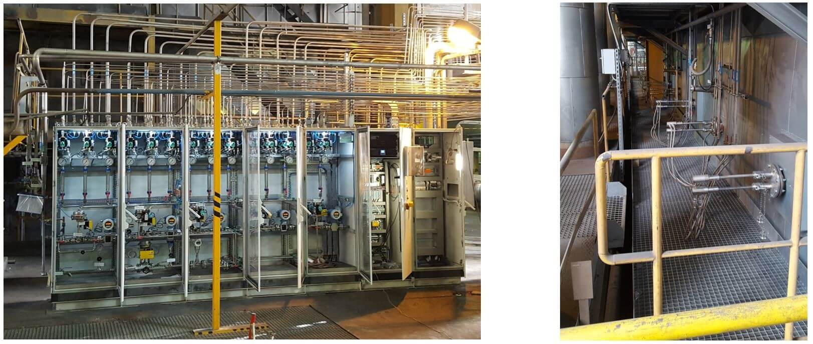
Figure 16: Location B - Mixing and metering module; Injection lances for reagent and selective cooling
The significant difference to Location A is that injection lances for Selective Cooling, installed below the highest injection level for the reagent, could be utilized because the flue gas temperatures in this position were lower than in Location A and the space between the front wall and the first super heater was larger, which resulted in a much better performance of the SNCR system.
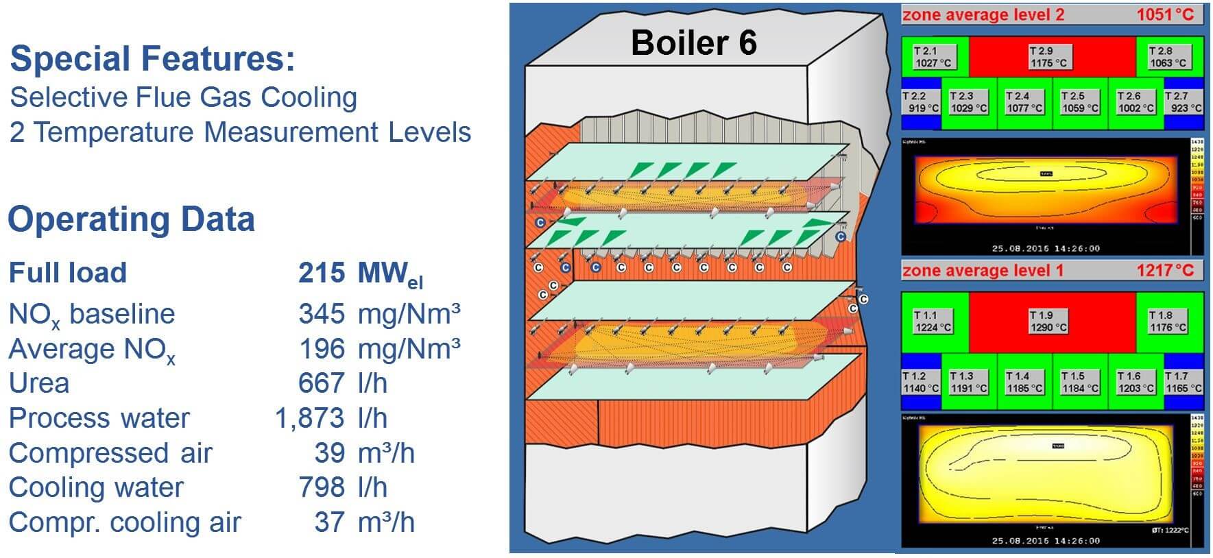
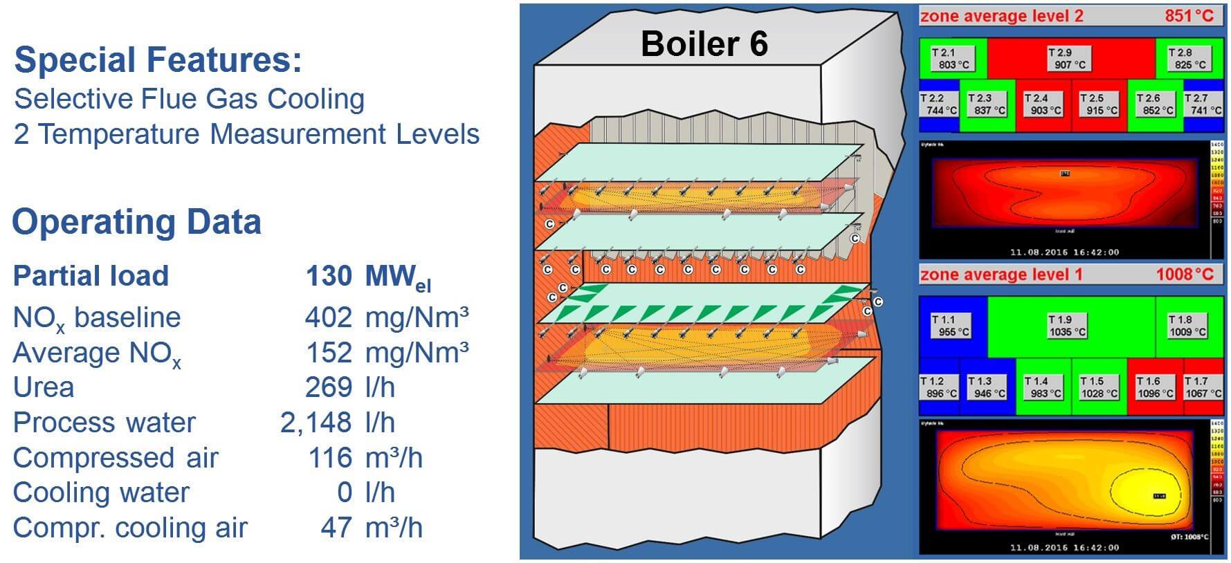
Figures 17 and 18 show the performance of the SNCR at boiler loads of 215 MWel and 130 MWel during the two weeks reliability run (Figure 19). All guarantee values were achieved at all loads.
Figure 17: Selective Cooling of flue gases - Operating data at full load (215 MWel)
Figure 18: Selective Cooling of flue gases - Operating data at partial load (130 MWel)
It is remarkable that the total water consumption which was an important issue during contract negotiations is approximately 1,000 l/h lower than the guaranteed maximum of 3,500 l/h and ca. 6,500 l/h lower than the consumption of the standard SNCR installed at boiler K4. These results demonstrate impressively that the Selective Cooling is superior to other SNCR technologies for the discussed type of power boilers and that a significant amount of operating cost can be saved.
Figure 19: Performance data during two-week reliability run at Location B
7. Adaptive Flue Gas Cooling
Injecting of water offers the great benefit that extensive and costly modifications of the boiler can be avoided when the flue gases are cooled down before entering the heat exchangers. The major disadvantage, however, is that depending on the operating hours at high boiler loads in which water cooling is necessary, the efficiency of the boiler is affected because of the energy needed to evaporate the water in the flue gas. Selective Cooling is already a big step forward to improve the performance of SNCR by cooling down the flue gases.
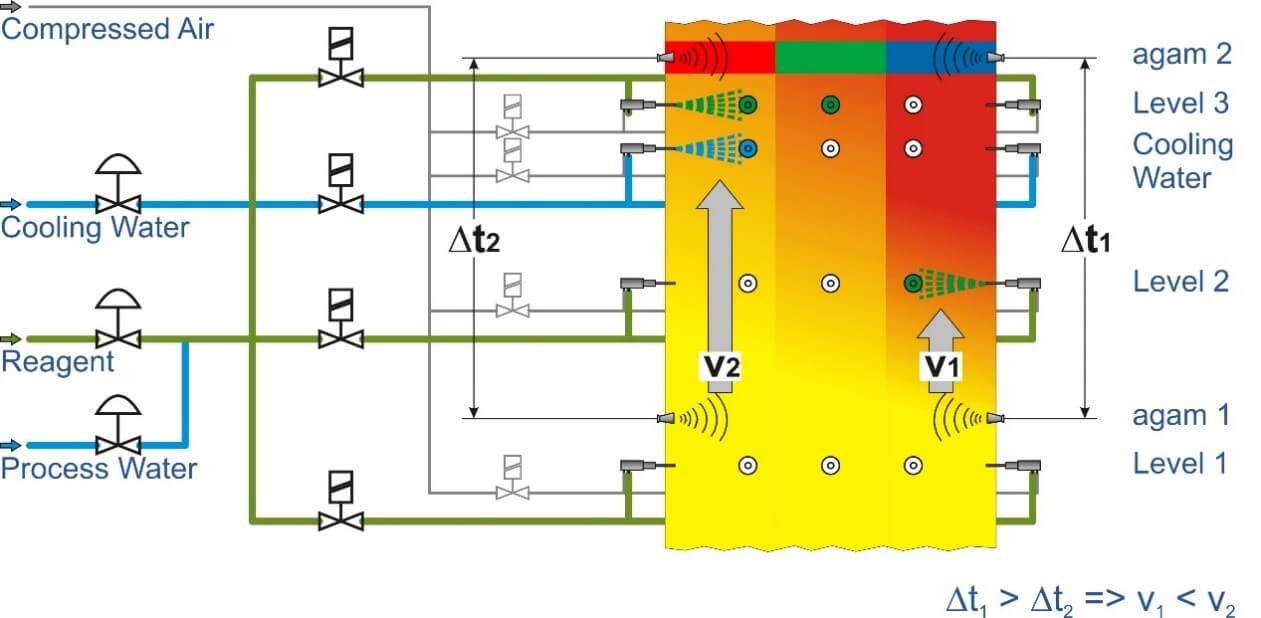
Figure 20: Principle of Adaptive Flue Gas Cooling
However, a better solution is to control the amount of water more precisely in order to further decrease the consumption of cooling water.
To realize this objective a temperature measurement system which generates a temperature profile has to be installed above the upper injection level in the furnace (Figure 20).
The temperatures are constantly being measured online and average flue gas temperatures are calculated in defined sections which are assigned to single injectors or groups of injectors.
Without injection of reagent
With injection of reagent only
With injection of reagent and cooling water simultaneously.
At the lowest level, injection of cooling water is generally not needed, since the injectors will be switched to higher levels as the flue gas temperatures increase with the load.
With the described concept the temperatures and the influence of the injected liquids, i. e. reagent/water-mixture and cooling water, can be measured. Based on the various temperatures the flow of cooling water can be adapted as needed to maintain the optimum temperatures within the injection level in order to obtain efficient NOx reduction and low ammonia slip. Furthermore, the activation of the lances for reagent can be determined more precisely when temperatures are measured in two levels.
To achieve this, another temperature measurement system has to be installed for measuring the flue gas temperatures above the lowest injection level as described for the top level.
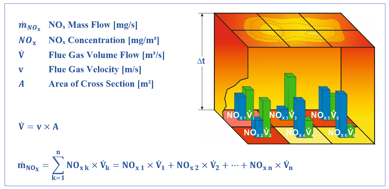
1.1. Defining Flue Gas Velocity
It is often neglected that apart from the flue gas temperatures, the flue gas velocities at different injection positions, are of equal importance for the efficiency of the SNCR process. The NOx to be reduced depends on the NOx baseline at the injection locations and the target NOx.
NOx mass flow [kg/h] = NOx concentration [mg/m³] * flue gas mass flow [m³/h]
There is high probability that in some areas where the flue gas velocities are low, too much reagent is injected in areas with similar NOx concentration causing higher ammonia slip since the reagents do not find enough partners for the chemical reaction. To avoid this, the flow of reagent should be reduced or stopped to decrease the consumption of reagent and minimize ammonia slip.
With this arrangement of the temperature measurement systems in two levels, the temperatures in the levels and sectors can be compared and the temperature gradient between the levels can be defined more correctly than with traditional methods.
Since hot flue gases have a higher natural draught and slower flue gases are cooled down more at the boiler walls and heat exchangers, higher temperature differences indicate a slower flue gas velocity compared to areas with smaller temperature differences (Figure 21).
This information is the basis to control, respectively adjust the flow of reagent to the corresponding injectors or groups of injectors with the objective to optimize NOx reduction and to minimize ammonia slip.
Figure 21: NOx Mass flow profile
If measuring equipment were used which provides data of other components like NOx, CO, O2, etc. in addition to the temperatures, these data could be incorporated into the control of the SNCR as well as into a further optimized distribution of the reagent across the furnace for better performance of the SNCR.
8. Summary and Outlook
In smaller combustion plants, e. g. those which burn waste or biomass, the SNCR process represents an industry standard and state-of-the-art method. In the meantime, operating experiences in large combustion plants with a capacity of > 200 MWel have shown over the past few years that SNCR can safely and reliably achieve the NOx level < 200 mg/Nm³ which has been enforced by EU legislation in 2016. Different injection concepts can be used separately or in combination in order to guarantee yearly average NOx levels of < 175 mg/Nm³ for lignite-fired boilers and < 150 mg/Nm³ for hard-coal fired boilers in the future.
The initial results of the newer technologies, like the changing of individual lances, the TWIN-NOx® process, the Selective Cooling and the combination of these methods with primary measures indicate that there is further potential for developments. The next step will be plants with boiler capacities from 300 to 500 MWel.
9. Literature
von der Heide, Bernd: “SNCR-process – Best Available Technology for NOx Reduction in Waste to Energy Plants”, Power-Gen Europe, Milan, June 3 – 5, 2008
von der Heide, Bernd: “Advanced SNCR Technology for Power Plants”, Power-Gen International, Las Vegas, December 13 – 15, 2011
von der Heide, Bernd: “SNCR-Verfahren der Zukunft für Großfeuerungsanlagen – Konzepte, Erfahrungen, TWIN-NOx®-Verfahren“ in: Michael Beckmann, Antonio Hurgado (Hrsg.): Kraftwerkstechnik – Sichere und nachhaltige Energieversorgung – Band 4. Neuruppin: TK Verlag Karl Thomé-Kosmiensky, 2012, S. 623 – 635
Moorman, Frans; Stubenhöfer, Claus; von der Heide, Bernd: „Replacement of an SCR DENOX system by a highly efficient SNCR in a waste-to-energy plant in the Netherlands“ in VGB POWERTECH Volume 93 – Issue 12/2013
von der Heide, Bernd: „Cost Savings and Improvements of SNCR Performance with Selective Cooling in Coal-Fired Boilers (225 MWel)”, VGB Workshop “Flue Gas Cleaning”, Lisbon, May 3 – 5, 2017